|
Introduction
Seismic surveys are divided into land and marine surveys. Although
the land seismic equipments are quite different than the marine
one, the source, receivers and acquisition equipments have same
exploiting logic. Marine seismic is quite harder than the land seismic
because of the challenging environments. In marine seismic, the
need for a good ship and powerful sources, receivers and acquisition
equipments are obligatory. As in the land seismic, 2-D and 3-D seismic
surveys can be done for scientific purposes. This characterizes
the necessary equipments for survey. The seismic survey can either
be important for monitoring the shallow structures with high resolution
or deep structures with low resolution. To achieve successful results
in seismic survey, the true equipment selection must be necessary.
Another reason for the importance of true equipment selection is
the high cost of the marine seismic surveys. It is not profitable
to repeat the survey.
The seismic tools can be divided as source, receivers and acquisition
control. The following sections are related to the detailed information
about these equipments.
Three short movies (format .MOV) from the survey are available (property
of Emre
Unal):
- Preparation of the
Sparker source (electrod cleaning)
- Launching the streamer
- Shots recording during the
experiment
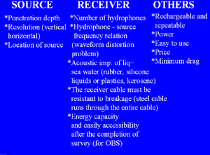
Sources
Penetration depth and vertical/horizontal resolution are the most
important factors in seismic surveys. These criteria are mostly
depending on the source types. TNT, Water Gun, Air Gun, GI-Gun,
G-Gun, Aquapulse, Air Gun arrays, Clusters, Boomer, Sparker, Flexichoc
and Side Scan Sonar are the most preferable sources. These sources
are used in terms of the main objectives of the seismic surveys.
TNT: This source was popular in the beginning of marine seismic
surveys. The main advantage of TNT using in surveys is the presence
of deep penetration capability. This advantage was actually the
only positive side of this source. The disadvantages can be classified
as:
1. Bubble effect caused by; heat occurrence during the explosion
and emission of water vapor. The water vapor is the main cause for
bubble occurrence after the explosion. This bubble effects the initial
arrivals of seismic waves in terms of noise. As an example, if 20kg
TNT explores, the bubbles formed due to the high heat need approximately
200msec to start contraction. The contraction results in the decreasing
of bubble in volume. The large time needed for bubble contraction
will affect the resultant seismic data due to the very large oscillating
bubble effect.
2. TNT is not a good choice for environmental reasons since the
explosion can cause some damages in the ships and economic and biological
loss.
3. The seismic survey made by TNT has low vertical and horizontal
resolutions.
4. TNT is not easy to use due to the unconfined explosion.
5. TNT is one of the sources, which is used for deep seismic surveys.
This results in the necessity of special receivers which consist
of special out-put characteristics of cable and attached depth controllers.
WATER GUN: One of the positive sides
of the water guns is the presence of low amount bubble effect. The
frequency interval is between 20hz to 1500hz. This also suggests
that the water guns are suitable for shallow seismic. After the
shooting, the trouble in rearming of the gun is the most important
disadvantages. The fragility and the presence of vacuum bubble effect
are the other negative sides of the techniques.
AIR GUN: Air guns are simple to use. They don’t
need lots of power to rearmed. The most important negative sides
can be:
1. The explosion can cause bubble formation in the water column
and this eventually causes unwanted noise.
2. The seismic waves formed after the explosion may be reflected
from the sea surface, which can cause unwanted signals on the data.
These signals are called ghost signals.
3. Presence of low resolution data
4. Fragile out-put characteristics of receivers cable (as in the
TNT).
G-GUN: G-Guns are one of the air guns which is confidence and do
not need the recoiling. The air used in the steel cylinders can
be used for 500000 shots repetitively. The fragile out-put characteristics
of the receivers and low-resolution seismic data are the main disadvantages
of this gun.
GI-GUN: The air exploring inside the steel cylinder
has a very low internal pressure with respect to the outer environment.
To decrease the pressure difference, an injection (I) towards the
bubble must be necessary. This will result in decreasing the inner
bubble pressure. This causes the preventation of the collapsing
the large bubble instead of formation of many bubbles. Many bubbles
are much worser than the single large bubble in terms of affecting
the data. The high P/B ratio ~20 is caused by decreasing bubble
effect. GI-Guns have more air volume than G-Guns, which increases
the shooting repetition. As a negative sides of the GI-Guns, low
resolution and fragile out-put characteristic of the receivers cable
can be counted.
AQUAPULSE: The aquapulse technique in seismic
sources has some similar properties of the air guns and water guns.
Instead of exploring water or air, propane-oxygen mixture is explored
inside the steel cylinder. This will cause diminished bubble effect
in the resultant data. Each explosion needs 8 second to rearmed.
This time interval is thought to be most important negative side
of this source types. Low resolution and fragile out-put characteristics
of the receivers are the other negative sides of this source.
AIR GUN ARRAY: Air gun arrays are different than
the other types of air guns in terms of the configuration of the
source and receivers. The receivers are oriented in arrays in order
to decrease the bubble effect. The multidirectional source and receiver
orientation are the characteristics of this source. This source
has the same disadvantage as low resolution and fragility receiver
cable.
CLUSTERS: To increase the shooting power, coalescence
of bubble and P/B ratio, combined sources are used. GI and G Guns
can be used as well as G Gun Parallel and Linear Clusters. One of
the most important reason for developing the clusters is to decrease
the bubble effect which influence data.
BOOMER: The electricity is one of the easiest
and cheapest ways in marine seismic exploration as well as air,
water and gas. One of the unique characteristics of the electricity
usage in seismic exploration is the need for high-resolution shallow
surveys. For high-resolution survey, high frequency (300hz to 3Khz)
seismic waves are produced. This high frequency seismic waves result
in monitoring the interval between the resolutions of 0.5 to 1m.
This high frequency waves can not go deeper (25 to 50m). The special
receivers are needed for high frequency seismic survey. The compatibility
of the source and receiver is the key factor in high resolution
seismic. These special receivers can also capture the huge amount
of noises in the nature (microseismic waves). Thus the high amount
of noise problem is one of the main disadvantages of the electric
sources.
SPARKER: Sparker is the another electrical source
for marine seismic. The 50Hz to 4kHz high frequency band is very
good for high resolution (1m) surveys. The sparkers are easy to
use and cheap. Sparkers are very good for high resolution seismic
and low penetration studies. The electricity power can be very high
(1000 joules or 400 kw). There is also a bubble effect which generally
occurs due to the increasing temperature during the shooting. Like
the boomer, the receivers must be high frequency compatible. The
high noise is also a big problem in sparkers.
FLEXICHOC: The seismic surveys consisting of flexichoc
is for high frequency and low penetration (50 m) researches.
SIDE SCAN SONAR: Side scan sonars are generally
used for detection of the underwater objects (ships, large fish
groups, archeological purposes…etc). Due to this reasons,
high frequency and very high resolution needed (3.5Khz).
Recorders:
There are many different recorders for different purposes.
*DELPH (France, CNRS)
*Sercel SEAL (SN 408) SEGD (France,Ifremer)
*Syntron Syntrak 480MSRS SEGD (Germany, BGR)
*Geometrics ES2420 SEGD (Germany, AWI)
*Geometrics Strata View RX96 SEGD (DAT) (UK, NERC)
*Texas Inst. DFSV SEGD (exabyte) (SPAIN, NRA)
*Texas Inst. DFSV SEGY (NORWAY, BERGEN UNIV.)
Receivers:
The receiver selection is very important since the
2-D or 3-D configuration is generally related with the receivers.
Number of channels and hydrophones are important in developing the
most successful seismic survey.
OBS receivers are only the receivers located on the sea floor. In
this type of receiver usage, the energy of the OBS and accessibility
to the OBS are the main important sides of the survey.
*Digital Sercel : 360 channels, 4500m
*Digital Syntron: 120 channel,s 3000m
*Analogue: 96 channels, 2400m
*Analogue Teledyne: 96 channels, 2400m
*Analogue Teledyne 40508: 96 channels, 2400m
*Analogue Fjord Instrument: 120 channels, 3000m
*OBS
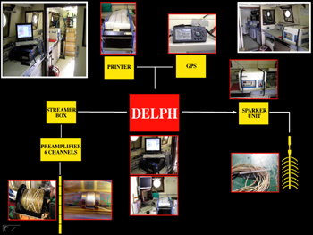
The above information mostly about the sources and receivers are
good for comparison of different elements in seismic surveys. Between
30th Monday and 31st Tuesday, 2005; a seismic survey was made in
NW Brest, France to monitor shallow geologic structures. The 2-D
seismic survey was made by the ship Cote de la Manche belongs to
CNRS. As a source sparker, 6 channels receiver and streamer box
were used. For the acquisition of the data, DELPH was used. One
printer and GPS was connected to the acquisition unit. The successive
steps and the detailed information about this high frequency seismic
survey is as follows:
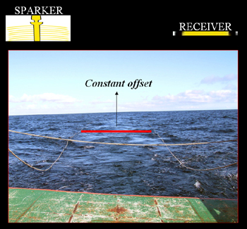
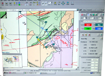
The delph unit triggered the sparker unit and electric current formed
(1000joules, 400kw). The electric transmitted between the cupper
wires of two end of sparker. Every 1.555sec a new shot was produced.
The sparker was located 60m away from the boat. After shooting,
the reflected high resolution seismic waves were detected by the
6 channeled receiver which was also located 60m from the boat. The
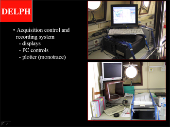
offset between the source and receiver was constant. By the help
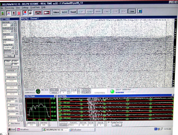
of the DELPH unit, having displays, PC controls and monotrace printer,
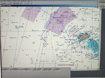
the data was monitored in the OziExplorer software. This software
was both for monitoring the seismic section immediately coming from
the receivers but also helps to navigate the seismic survey. The
GPS was connected to the software and the speed and cap via was
observed from the screen. The geological structures were also monitored
during the seismic survey. Different monitors in the software program
contribute to understand the seaway traffic as well as the bathymetry,
coastline location and possible currents. The number of shots and
first initial arrival of seismic waves were monitored by the help
of this program. The lat and long of the followed routes of the
seismic survey was continuously observed. The lat and long and their
continuous recording was vital in order to make a successful seismic
survey. Each route and its seismic profiles were then interpreted
geologically
Conclusions
There are many different types of sources and receivers.
The objective of the seismic survey is important for selecting these
seismic tools. The below figure shows relation between periods of
bubble oscillation and amount of energy in different sources. Although
the TNT has the highest seismic energy capability, the huge bubble
oscillation effect makes TNT as a less favorable source. Whereas,
the boomer and sparker has the least bubble oscillation effects
with the low amount of seismic energy.
The explosive sources are powerful however their low mobility and
difficult usage makes them unpopular. The air guns, gas guns, sparker
and boomer are the most preferable sources in marine seismic surveys.
For the low frequency and deep penetration studies, air guns and
gas guns are preferred. The sparkers and boomers are preferred for
high frequency and low penetration studies.
|